Basepump
Detailed Basepump installation instructions


“Ask for it by name”
Basepump® Installation:
These are GENERAL drawings to illustrate basic, typical installations. Basepump is easily adapted to almost any application including longer discharge runs, offset suction pipes, low ceilings, sealed radon covers, under staircases, in closets and crawl spaces, etc. It is not limited to the simplified drawings here; if we tried to present every possibility, we’d have hundreds of sketches and too much confusion. Call or email us if you have questions.
Watch Video of an Installation:
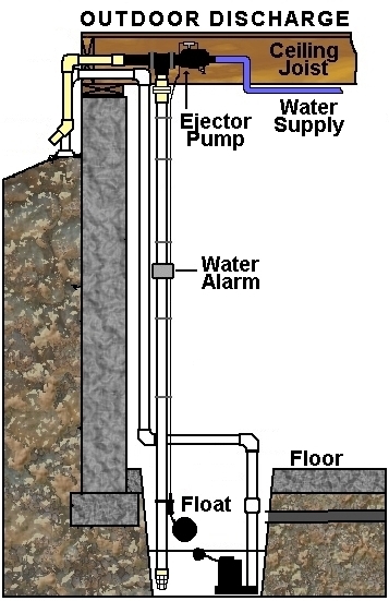
Here we have a professional plumber installing a standard Basepump Model RB750. This is a typical Outdoor Discharge Installation that connects to the underground storm drain shared by the gutter downspout and primary sump pump. It is pretty self-explanatory.
Basepump Suction and Discharge Options – Some Common Examples of Installations
Can I save money by doing it myself? How do I know if this is a project I can tackle?
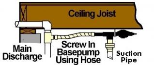
Under Joist Discharge

Basepump mounted underneath ceiling joist with flexible discharge hose sloping upward and out through exterior wall.
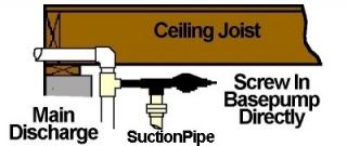
Perpendicular Discharge
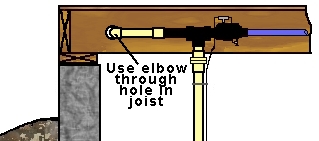
Basepump mounted perpendicular to ceiling joist, discharged at right angle from pump through hole in joist to exterior.
Suction Pipe Installation Options
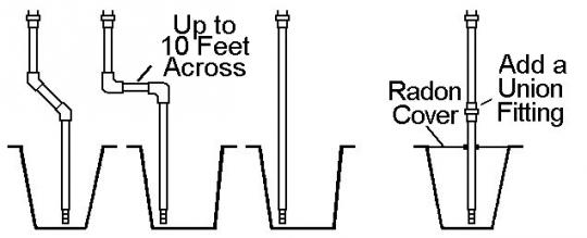
These are 4 typical sumps drawn here. Each one shows the suction pipe from the Basepump in a different way. From left to right:
- is offset using 45 degree elbows
- is offset using 90 degree elbows; the horizontal length may be up to 10 feet across
- is straight up and down
- is straight up and down through a Radon Gas sealed cover.
This shows how simple it is to clear obstacles or to make installation easier. The pump may be installed up to 10 feet away horizontally from the sump, because there may be stairs, heating ducts, electrical panels, cabinets, shelves, windows, or whatever, in the way.
Indoor Discharge
-
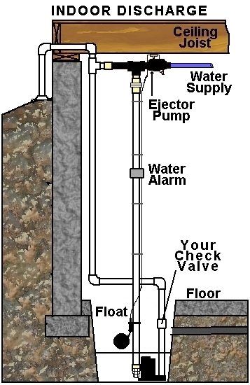
Basepump is designed to be discharged independently outdoors, separate from your primary sump pump discharge pipe. However circumstances may make it necessary to connect the discharge indoors into the primary sump pump pipe.
-
Please take note: Carefully consider the following when connecting the discharges together indoors:
- Your primary sump pump discharge pipe MUST have a good quality, working check valve installed between the primary sump pump and the tee-in point for the Basepump. If this check valve fails, Basepump will be able to send water back down through the primary pump and the basement will flood.
- If your primary sump pump discharge pipe becomes clogged or frozen, then Basepump will also not be able to operate and the basement will flood.
- The Unified Plumbing Code (UPC) prohibits the discharge of a water powered pump into the primary discharge pipe, in most cases.
- The drawings below illustrate how to keep the suction pipe as a separate pipe and run the discharges out together.
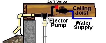
Install with AVB Backflow Preventer
Note: When using the – AVB add-on, the discharges must not be connected together indoors at all.
The discharge for Basepump in this application must be self-draining to the exterior. Any connection to a drain outside MUST have an air gap to prevent blockage or back siphon to occur, rendering the AVB inoperable. See Back-flow Prevention.
BASEPUMP WATER SUPPLY PRE-INSTALLATION CHECKLIST
Important! Pre-Qualify Your System
Pre-Installation 4 Point Checklist
Before installing, use this handy checklist to verify each item below. Improper installation will result in reduced pumping capacity or pump may not operate at all. Each pump model has slightly different requirements so take note of each model number and the information associated with it.
1. Household Water Pressure
Minimum: 40 lbs. PSI
Maximum: 90 lbs. PSI
Compensate for normal pressure loss from test point to Basepump location. Avoid excessive piping from “tee-in” location, whenever possible. If incoming municipal water pressures exceed 90 lbs. PSI, then it is necessary to “tee-in” after the Pressure Regulator Valve (PRV) to protect the pump valve from damage.
2. Household Water Flow – Extremely Important, DO NOT SKIP THIS TEST
You must be able to fill a bucket with five gallons of water from an outside hose spigot at the following rates:
RB750: 40 seconds or less
HB1000: 30 seconds or less
CB1500: 20 seconds or less
This test is often misunderstood. The idea is that the spigot coming from a typical 1/2″ water line, closely resembles the internal dimensions of Basepump. It is necessary for your water supply to be able to put 5 gallons of water through the pump in the allotted time as shown above, without having to install the pump first.
If it takes longer, you may have a restriction that must be bypassed or removed to maximize pumping capacity. If your reading is on the border of these numbers, you may select either one. Keep in mind that you can always get the smaller model, but not always the larger one. Example: you get a reading of 30 seconds. You may choose either the RB750 OR the HB1000. The RB750 will run at the higher end of its range 800-900 GPH, but the HB1000 will run at the lower end of its range 900-1000 GPH. The difference may be very small between them. “Frost-Free” spigots restrict flow by about 25% so adjust the time you measure by reducing it by 25% (multiply the time you got by .75) after you fill the bucket. (e.g. A 40 second “frost-free time” would adjust to 30 seconds “regular spigot time”), allowing us to use the same chart for both types.
3. Type of Piping
RB750: 1/2″ or 3/4″ Pipe
HB1000: 3/4″ Pipe
CB1500: 3/4″ or 1″ Pipe
Must be installed using copper, CPVC, OR PEX pipe (check local codes if unsure) in the sizes indicated above. DO NOT connect to or install using galvanized iron pipe. The potential for rust and debris to break loose could hinder pump from operating properly.
Pipeline Restrictions
No Restrictions
Basepump must be teed-in before any devices that restrict water flow. Examples of such devices are: stop & waste valves, globe-type valves, some pressure regulator valves (PRV), water softeners, filters, etc. Water meter must be minimum 3/4″ standard (usually marked as 5/8″). A Dual Check Valve or an SVB (Spill-Resistant Vacuum Breaker) Backflow device installed in the water supply line before Basepump is often required and should pose no problem. The more flow-restrictive, Reduced Pressure Zone (RPZ) devices will often prevent Basepump from operating. We offer backflow devices in several versions as optional equipment. We have a dual check valve, a vented dual check valve, and an Atmospheric Vacuum Breaker (AVB) device. If you are unsure if you need one, take a look first and then contact your local plumbing department if you have any further questions. Refer back to point #1 if incoming pressures exceed 90 lbs. PSI
General Information
This is NOT a complete instruction manual. It is an overview of the most important details to help you determine if Basepump is the right fit for your application. Complete instructions are included with your pump.
Please READ all the instructions that come with the product BEFORE attempting to install Basepump. The average pumping capacity of Basepump may vary depending on your municipal water supply, pressure, and any restrictions that may exist in your piping. DO NOT connect Basepump BEFORE the Water Meter. This is stealing water and is a crime. DO NOT OVER TIGHTEN FITTINGS WHEN CONNECTING TO BASEPUMP!! DO NOT APPLY HEAT DIRECTLY TO BASEPUMP!! MAKE COPPER CONNECTIONS SEPARATELY AND THEN THREAD THEM INTO BASEPUMP AFTER THEY COOL! Damage to the pump unit can occur if this is ignored and will VOID THE WARRANTY!! Ask your plumber about adding a shut-off valve right after the Basepump Tee-in point so you would be able to turn off the water to the rest of the house and leave Basepump operational; GREAT FOR VACATIONERS.
Additional parts or supplies needed:
- RB750 can be installed using 1/2″ or 3/4″ copper pipe or equivalent; 1″ PVC Suction & Discharge pipe
- HB1000 is installed using 3/4″ copper pipe or equivalent; 1-1/4″ PVC Suction & Discharge pipe
- CB1500 can be installed using 3/4″ or 1″ copper pipe or equivalent; 1-1/2″ Suction & Discharge pipe.
The following pipe and fittings are typically used in the installation process. Your application may be different than this, so you must plan accordingly.
- Copper (or equivalent) pipe and fittings, usually a tee, a couple 90 Degree elbows, and enough pipe to connect your existing water supply to the inlet fitting of Basepump.
- Full Flow “Ball” or “Gate” Valve.
- Union fitting
- Dual check valve or Atmospheric Vacuum Breaker to prevent back-flow into the potable water supply may be needed. Check with your local Plumbing Department to be sure.
- Female adapter to connect to 3/4″ threaded male fitting on Basepump.
- Clear PVC cement and pipe thread sealant tape or paste.
- PVC pipe for the suction line in the proper size for your pump model and enough to fit your application.
OR
Take a look at one of our easy-to-use, No-Sweat Installation Kits. These kits come in 1/2″ and 3/4″ sizes and are easy to use with either copper, PEX, or CPVC piping systems. They can even be used to convert from your existing copper to the newer PEX systems without special adapters. You get everything you need for most typical installations, except the pipe itself. That can be purchased locally in either rigid or flexible form. Note: RB750-EZ and HB1000-PRO both include these items in the box. Click here for price information or to order your kit today.
Tools Needed:
- Power drill with screwdriver bits.
- Hole saw attachment is needed for outdoor discharge installations. Hole saw size for each pump: (RB750: 1-1/2″ HB1000: 1-3/4″ CB1500: 2″ ).
- Phillips and Slotted Screwdrivers.
- PVC cutter or saw, Utility Knife and Tape Measure.
- Plumbing tools for the water supply pipe you are using.
Product Specifications
- Materials: Heavy-duty Schedule 80 Polypropylene, Stainless steel hardware, PVC fittings
- Dimensions without check valve: RB750: L: 16″; W: 4″; H: 6″; Wt: 1.5 lb. HB1000: L: 16″; W: 4″; H: 7″; Wt: 2 lbs. CB1500: L: 18″ W: 4″; H: 9″; Wt: 4 lbs.
- Water inlet fitting: RB750 & HB1000 – 3/4″ Female; CB1500 – 1″ Female. Male nipples & reducers included.
- PVC Suction and Discharge openings: RB750- 1″ Socket; HB1000: 1-1/4″ Socket; CB1500- 1-1/2″ Socket)
- Water service requirements: Minimum pressure: 40 PSI Maximum pressure: 90 PSI
- Water Flow minimum rate required: RB750- 7GPM; HB1000- 10 GPM; CB1500- 15 GPM